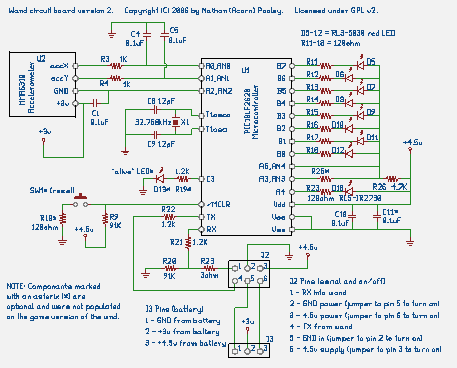
The hardest part of this project was the software; the circuit is actually pretty simple. However the circuit had to be developed before the software, so this is where work began. Here is the schematic diagram for the wand circuit board.
I chose the Microchip PIC microcontroller because I am familiar with programming them. We ran out of program memory when working on the DRUID (which had 16K), so I wanted plenty of it (the 18F2620 has 64K of flash memory). I also needed a bit of RAM to process all the accelerometer data (the 18F2620 has 3968 bytes of RAM). Finally I needed the A/D converters which the PIC has built in. I used the LF version of the chip to reduce power consumption and so that the wand would continue to run even after the battery voltage drops.
I used the 10g 2-axis MMA6231Q accelerometer from Freescale. Freescale has a free sample offer on their website so I was able to get some of the parts quickly (and free) to play with. I was worried that the 1.5g parts (which measure up to 1.5 times the force of gravity) were going to max out with a quickly waved and tapped wand, so I went with the 10g version. The 10g version rarely maxes out (only when tapped really hard).
The accelerometer is easy to use. It has 2 pins for power (+3v and ground), and 2 pins for acceleration. The X acceleration pin produces a voltage which increases when the chip accelerates in one direction and decreases when it accelerates in the other direction. The Y acceleration pin is similar, but for the Y axis. Freescale also has 3 axis chips, but for a waving wand only 2 are really required. The biggest problem with the accelerometer is the tiny package with microscopic pins that are completely hidden on the bottom - more on that later.
I got the LEDs from superbrightleds.com because they realy do have much brighter LEDs than any others I've seen. I used the RL3-5030 which is red, has a 3mm package, produces 5000 mcd (milli-candella) of light power, and is brightest in a 30 degree cone.
The accelerometer X and Y pins are connected through a low pass filter (R3-4 and C4-5) to the PIC input pins. The AN0 and AN1 are analog to digital (A/D) converter input pins and they can sense different voltage levels and report a 10 bit number which indicates the voltage on the pin.
To keep the accelerometer from drawing power when we are not using it the ground pin of the accelerometer is connected to the A2 pin of the PIC. Pin A2 is held low to turn the accelerometer on. To turn it off I put the pin in a tristate analog input mode. This is a high impedance mode, so very little current will flow. The voltage on the pin will be about 3 volts (since the other pin is connected to the +3v supply). Digital inputs like to be held high or low and can use more power when they are left in the middle (e.g. 3 volts), so a digital input would not be a god idea here, but that is not a problem when the pin is in analog input mode.
C1 is used to keep the supply voltage from fluctuating.
Each of the 5 LEDs on the wand is connected to a PIC output pin which controls it. The circuit has 8 LEDs, but we only used 5 in the production version of the wand (D5-D9). Each LED has a resistor to limit the current (R11-R15). The LEDs are turned on by setting the pin low, and turned off by setting the pin to tristate. I avoid setting the pin high to turn the LED off because some leakage might occur if the high state voltage on the pin is lower than the supply voltage.
When the wand is displaying text the LEDs are blinking on and off very quickly. Each time you see a red dot (part of a character) you are actually seeing the dot flash on and off 20 times (but it is so fast you just see a single dot). So when drawing text I want the LED to be at maximum brightness.
When the wand is just displaying dots (such as while levelling the wand or while casting a spell), however, turning the LEDs on at max brightness is too bright (blinding!). That is where R26 comes in. It reduces the amount of current that can flow in the LEDs and makes them dimmer. When we need maximum brightness (for text) then the A5 pin is set high and current is no longer limited by R26. R25 is there to support a 3rd level of brightness, but we did not need that.
A reset button is a good idea when debugging the wand, but it is not needed in the production version. In the production version SW1 and R10 are not poplated and the reset (which PIC calls MCLR for Master CLeaR) is held high all the time. The PIC has an internal power-on reset circuit so holding MCLR high all the time works fine.
On most of the microcontroller circuits I build I include an "alive" LED. This LED blinks on and off under software control to let me know that the program is still running. On the production version of the wand this LED (D13 and R19) are not included.
While the wand is displaying text or being used to cast a spell it is actually running off an internal 4MHz oscillator. However the internal oscillator is not very accurate. In order to keep track of what time it is I added X1, C8, and C9 are part of a 32.768kHz oscillator. The oscillator drives an internal timer.
The oscillator is also used when the wand is NOT being used. If the wand is not moved for a while (15 sec) it "goes to sleep." When it is "asleep" it is actually still running a program. However it turns off the 4MHz internal oscillator and instead runs of the 32.768kHz oscillator. This much slower oscillator causes the PIC to consume much less power. While "asleep" the PIC turns the accelerometer off. About 10 times a second the accelerometer is turned briefly back on and checked for motion. As soon as there is motion detected the wand "wakes up" and goes back to running at 4MHz.
I used the serial port on the wand for debugging and for loading new versions of the program. The RX andTX pins are connected to J2. A cable connected to J2 allows me to connect a laptop serial port to the wand and send messages back and forth.
The serial port uses RS232 protocol, but the signalling voltage varies only from Vss to Vdd (0 volts to +4.5 volts). Normally RS232 uses -12v to +12v signalling, and that is what the laptop exxpects. In order to connect the wand to the serial port you need something to covert the voltages back and forth. I use a MAX232 chip circuit which you can find on page 7 of the max232 datasheet.
Power is supplied to the wand from 3 AA batteries. The batteries are connected in series and a wire from the negative terminal and the positive terminal supply ground (0volts) and +4.5 volts, respectively. There is also a wire from between the 2nd and 3rd batteries which supplies +3volts. You can run the wand off of just 3volts by connecting the 3v and 4.5v inputs of J3 together and just supplying ground and +3v, but the LEDS are brighter and more consistant with 4.5 volts.
The J2 jack is the programming jack, but it is also used to turn the wand on and off. The +3volt supply is always connected, but the ground and +4.5volt supply from the battery are only connected from J3 to J2 pins 5 and 6. To turn the wand on J2 pin 2 is connected to J2 pin 5 (ground), and J2 pin 3 is connected to J2 pin 6 (+4.5 volts). This allows the batteries to be soldered to J3 while still being able to leave the wands turned off. To turn the wand on a jumper can be added, or the appropriate J2 pins can be soldered together. In the wands used in the game the J2 pins were soldered together (2 to 5 and 3 to 6).
C10 and C11 keep the supply voltage to the PIC from fluctuating too much. C11 is not needed and is not included on the wands in the game.
This file Copyright (C) 2006 by Nathan (Acorn) Pooley
Go to TOP Wand page
Go to Acorn's personal webpage
Go to Hogwarts website: www.gotohogwarts.com
Snout: www.snout.org/game
Gadgets of Justice Unlimited
File created by Acorn on Sat Sep 16, 2006