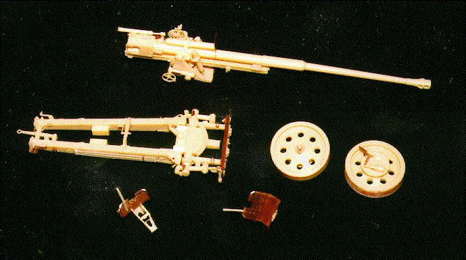
Precision Models' Pak 43/41 in 1/35 scale and 88mm Ammo Set in 1/35 scale
Gun:
Catalog number 35007B
Multimedia kit (resin, photo-etched brass, brass wire)
Approximately 267 parts (roughly 215 resin, roughly 50 PE, 2 diameters of brass wire)
Recommended for advanced modelers

Ammo Set:
Catalog number 35008Z
Resin, 55 parts
The Pak 43/41 was a powerful anti-tank weapon, feared by most Allied tank
crews. The gun itself was also mounted on the SdKfz 164 Nashorn as a
self-propelled anti-tank weapon. As a modeling subject, both this gun and the
earlier 88mm Pak 41 have been long neglected in injection plastic, though
the earlier gun has been available in resin from several different
manufacturers for a few years. In the last year, however, two different
companies have produced the later Pak 43/41 in resin, Verlinden Productions
and now Precision Models.
For reference as I built this kit, I used the following: Panzers at Saumur
volume 3, which has two pages of photos of this gun following their Nashorn
coverage; Panzerabwehrgeschutz 1934-1945, Waffen-Arsenal Band 117, by Werner
Haupt, which may be available in English from Schiffer Publications by now;
and finally (and most usefully) a set of photographs of a Pak 43/41 preserved
at the Aberdeen Proving Grounds in Maryland. Unfortunately, the first two
references were not of great help in building this kit. Photos of the real
thing taken in an open environment such as APG were much more helpful in
answering questions about the more complex assemblies.
The instructions consist of 4 pages printed on both sides, with one side of
one page being a parts listing. KEEP THIS HANDY. Many of the smaller parts
are not easily distinguished from the assembly diagrams. Always match by part
number, not by what it looks like in the exploded view. The clarity of the
instructions is lacking, and I hope to clear up the tougher points. In some
places, parts are mis-numbered. In most of these places, the makers of the
kit caught the error and corrected it, but I will clear up the errors that I
was able to find, that they had missed.
Assembly was pretty straight-forward, and I followed the recommended
instruction sequence they provide. Trouble points for me in step one included
cleaning too much material from the resin casting blocks, and cutting out some
thin areas I mistook for flash. Study the diagram carefully, and you will save
your self the trouble of trimming 0.010" styrene as I had to. Check and
double-check the placement of parts 60 and 61, using the inset exploded diagram
as well as the view of the area in Step 2. These parts can (and will) interfere
with the placement of the suspension arms. Step 2 was without alarm, but in
Step 3 I found it impossible to form the brass wire around parts 115 and 116
to make the lifting eyes. I used 0.020" solder instead, as it was more flexible
and formed much more easily. Do be warned ahead of time that the casting blocks
for the wheels (parts 1 and 2) virtually destroy the tread for about a
60-degree chord of the tire. Patient sanding to remove the flash, followed by
puttying and careful filing with some mouse-tail files did a decent (but not
perfect) job of restoring the tread on my wheels. Once I was done with Step 3,
I could hang the parts diagram, the reverse side of this page, up on the wall
near my desk for easier reference.
Steps 4 and 5 were perhaps the most enjoyable in the whole of construction.
I did Step 5 first, building the spades for the carriage arms. Note that the
two spades are NOT the same size, that part 149 is noticeably larger than 150.
Make sure that you match up photo-etched parts P72 and P73 go with part 149,
and that P70 and P71 go with 150. The side braces for the spades, P38, P39,
P40 and P41, do not quite fit against the sides of P48 and P49.
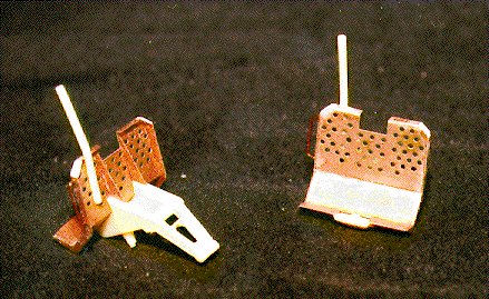 Use the resin
parts 149 and 150 to form the spades themselves, then trim the side braces to
fit the spades properly. I found that the side braces did not extend all the
way to the top of the perforated parts of the spades, so I trimmed them at the
last bend and bridged the last span with styrene strip. When done, and
including two pieces of styrene per spade, each spade weighed in at 12 pieces,
and both looked like gems. Step 4 held few surprises. Cleaning the casting
blocks from carriage arms 10 and 11 will take time. I replaced resin parts
A, B and C, the three-part cleaning rod, with styrene rod. The parts, and many
others, were cast on a thick backing block and required careful removal with
a razor saw, while trying not to damage a neighboring part or break the one
being removed. It was easier to replace them outright. Aside from those parts,
however, the rest of Step 4 went by the paper. There is a diagram showing how
the spades can rotate from folded to extended, but do not attach the spades
at this time. Do dry-fit them to become familiar with which goes on which side,
since no where in the instructions are you ever actually show to attach them!
I chose to leave mine off until painting, making handling the carriage less of
a risk.
Use the resin
parts 149 and 150 to form the spades themselves, then trim the side braces to
fit the spades properly. I found that the side braces did not extend all the
way to the top of the perforated parts of the spades, so I trimmed them at the
last bend and bridged the last span with styrene strip. When done, and
including two pieces of styrene per spade, each spade weighed in at 12 pieces,
and both looked like gems. Step 4 held few surprises. Cleaning the casting
blocks from carriage arms 10 and 11 will take time. I replaced resin parts
A, B and C, the three-part cleaning rod, with styrene rod. The parts, and many
others, were cast on a thick backing block and required careful removal with
a razor saw, while trying not to damage a neighboring part or break the one
being removed. It was easier to replace them outright. Aside from those parts,
however, the rest of Step 4 went by the paper. There is a diagram showing how
the spades can rotate from folded to extended, but do not attach the spades
at this time. Do dry-fit them to become familiar with which goes on which side,
since no where in the instructions are you ever actually show to attach them!
I chose to leave mine off until painting, making handling the carriage less of
a risk.
In Step 6, we build the gun itself. As I mentioned earlier, one can easily
remove too much material from a casting block and find that they also removed
a locator pin. This is very true on the two-part gun barrel. Part 143 should
have some of the casting pin left intact, as it acts as a locator into the
depression in part 142. Believe me when I say that aligning these two parts
without the locator is very frustrating. While most of the remainder of this
step is by the paper, some notes: cleanup of part 3 must be done carefully,
as other parts are to align with the bottom of 3. Parts that are labeled 25
and 27 on the diagram (which attach to 19 and 20, respectively) are in fact
parts 35 and 37.
Step 7 completes the assembly of the carriage, joining the arms to the base
that was built-up in Steps 1-3. In this step, the only reference to building
the gun in firing order is made. The positioning of parts for firing order is
not clear, however, so I chose to keep mine in traveling order. Few new parts
are involved in this step, and the instructions recommend joining the wheels
at this stage. I left mine off until after painting.
Step 8 is one of the more difficult, and deals with the construction of the
cradle for the gun. There are a lot of rods and wheels to get into a very
small space. This step also illustrates the positioning of part N between the
lower shield and the underside of the gun's recoil slide. Do this only if you
are building the gun in traveling order. For firing order, part N would be
swung downward. Do not attach N to the gun itself, as you will want to keep
them separate for painting.
At no point do the instructions actually cover attaching the gun to the cradle.
It should be done before proceeding to Step 9, as the gun may affect the sides
of the cradle, which should be done before attaching the shields. Carefully
spread the sides of the cradle and work the gun into the space between. I
found it easiest to use the flat surfaces of 19 and 20 on the gun to slide
along the mounting pins in parts 104 and 105 of the cradle. Those pins (on 104
and 105) will eventually mate up to the holes on 19 and 20.
Step 9 is hands-down the most difficult part of construction. Give yourself a
lot of time, and allow for a lot of patience. First, the shields themselves.
The pak 43/41 shared the 75mm Pak 40's two-layer baffled-style shield design.
In this kit, it is beautifully done with photo-etched shield sections and
resin lugs to represent the spacers used to attach the two shields together.
but construction is a bear. I lost a lot of the resin lugs (part number 133),
and wound up scratch-building replacements for more than half of the lugs used
on one of the two sides. The worst aspect, however, is that the shields
themselves are so finely engineered, that the holes for the lugs are positioned
so that the fit is perfect, once assembled. That means that until you have both
layers in place with respect to each other, one will not fit over the other
with the lugs in place. I had to line up on as many lugs as I could, then
gently force the outer shield over the remaining lugs until it snapped into
place (and a snapping sound is NOT what your ears want to hear at that time).
It took several tries, as the outer shield kept bending out of shape and had to
be re-formed. Once both sides of the shield are done, take a break from the
project for a bit, and catch your breath. When done, they are as nice-looking
as the spades, but the work to get them there is considerably greater. One
vary important note: once the shield sections are together, there will be no
getting paint in between them, no matter how fine a stream from the airbrush.
While I opted not to prime the parts for the sake of the in-progress photos,
I did prime the inside surfaces of the shield sections with Floquil's
Gunmetal, ensuring some shade other than natural brass, should someone shine a
light in the gap at a contest. Now that the shields are done, you get to
attach them to the cradle. Unfortunately, the arms (parts D, F and R for the
left half, and E, G, and P for the right) do not have exact guiding pins for
their attachment to either the cradle OR the shields (in fact, the attachment
to the shields is by parts 156, whose angle with respect to the arms hinges on
correct attachment to the cradle). In short, this was the single most
frustrating part of the project, more so than even the shields themselves.
Once done, it is great. Getting there can be painful. When the shields are
attached, the rest of the bits follow very easily.
 The last step brings the whole gun assembly (cradle and all) to the carriage.
At this point I would also attach the wheels, and the spades would already
have been attached. Before Step 10, I attached the spades to the carriage,
and proceeded to paint and weather all components. I painted the whole gun and
carriage a color meant to resemble Panzer Dark Yellow, mine being a mixture
of Floquil's Panzer Dark Yellow (which I consider too light) with about 20%
by volume dark brown. The result is a little darker, more earthy tone.
Everything got this color, then the breech and some gun components got
varying shades of black and gray, rubbed down with powdered graphite for
a worn-metal look. The wheels were masked off and the tire painted a base
color of Humbrol's Tank Grey (67). When this had dried, I "rubberized" it
using a treatment of Burnt Umber and Ivory Black artist's oils. A Burnt Umber
wash was applied over all details, particularly the prominent bolt detail
on the carriage arms and the protruding pins of the lugs on the shields.
Once the wash had been blended in and allowed to dry, I dry-brushed the whole
area (minus the tires and gun breech) with un-tainted Floquil Panzer Dark
Yellow. After the oils on the tire dried and the dry-brushing elsewhere had
dried, I gave the whole gun a coat of Testor's Dullcote (still my favorite
pick for flat finishes). This sealed the finished, and took the shine off
of spots where the thinner in the oil wash was still a little glossy.
The last step brings the whole gun assembly (cradle and all) to the carriage.
At this point I would also attach the wheels, and the spades would already
have been attached. Before Step 10, I attached the spades to the carriage,
and proceeded to paint and weather all components. I painted the whole gun and
carriage a color meant to resemble Panzer Dark Yellow, mine being a mixture
of Floquil's Panzer Dark Yellow (which I consider too light) with about 20%
by volume dark brown. The result is a little darker, more earthy tone.
Everything got this color, then the breech and some gun components got
varying shades of black and gray, rubbed down with powdered graphite for
a worn-metal look. The wheels were masked off and the tire painted a base
color of Humbrol's Tank Grey (67). When this had dried, I "rubberized" it
using a treatment of Burnt Umber and Ivory Black artist's oils. A Burnt Umber
wash was applied over all details, particularly the prominent bolt detail
on the carriage arms and the protruding pins of the lugs on the shields.
Once the wash had been blended in and allowed to dry, I dry-brushed the whole
area (minus the tires and gun breech) with un-tainted Floquil Panzer Dark
Yellow. After the oils on the tire dried and the dry-brushing elsewhere had
dried, I gave the whole gun a coat of Testor's Dullcote (still my favorite
pick for flat finishes). This sealed the finished, and took the shine off
of spots where the thinner in the oil wash was still a little glossy.
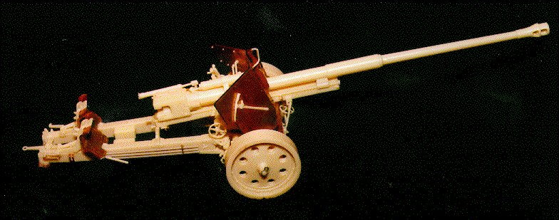 Once the gun was joined to the carriage, I found that the wheels did not go on
as they were supposed to. According to my photos, the wheels should go as the
instructions say: the hydraulic arm portion of the "triangle" on the back of
the wheel should be parallel with the carriage arms. But trying this showed
that the rest of the assembly on the back of the wheel was crowded out by
the bottom corner of the shields. Whether this means that the shields are too
wide, or the axles too short, I cannot tell from photos. I chose to rotate the
wheels towards the rear until the offending hardware on the wheels was rotated
out of the way of the shields. My Pak 43/41 is now complete:
Once the gun was joined to the carriage, I found that the wheels did not go on
as they were supposed to. According to my photos, the wheels should go as the
instructions say: the hydraulic arm portion of the "triangle" on the back of
the wheel should be parallel with the carriage arms. But trying this showed
that the rest of the assembly on the back of the wheel was crowded out by
the bottom corner of the shields. Whether this means that the shields are too
wide, or the axles too short, I cannot tell from photos. I chose to rotate the
wheels towards the rear until the offending hardware on the wheels was rotated
out of the way of the shields. My Pak 43/41 is now complete:
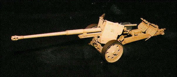
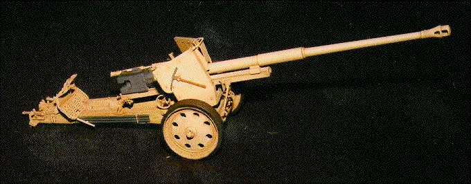
This review may appear to paint an unflattering picture of this kit, but in
truth, it is a seemingly very accurate kit, that is packed to the hilt with
detail. Some areas are over-engineered, using several parts when one will do.
Parts are very delicate and easy to lose (I lost and recovered and re-lost
dozens). But the final product is a very impressive rendition of a very
significant gun in the German Army's arsenal of World War II. This kit is
most certainly recommended to advanced modelers (more advanced than I, I
should admit), and at the price of around $80, it will really only appeal to
the connoisseur of towed artillery, especially when the Verlinden kit is only
around $50. I cannot compare the two, not having seen the Verlinden kit, but
I took about 120 hours over the course of nearly 4 months finishing this kit
(much of that time on my hands and knees looking for the just-dropped part),
with more time spent on the shields and carriage spades than any other aspect
except for painting and weathering. The finished gun on my display shelf
is worth all the time spent wrestling with shields and hunting lost parts.
I have not spoke about the Ammo Set yet, as I would only have used it in this
project had I built the gun in firing order and put it on a base. But the
ammo itself is wonderfully done. The package contains 20 empty shell casings,
15 shell tips of 3 different styles, 10 container crates and 10 wicker cases.
All casting is very crisp and clean, and to test I fit one each of the three
types of warheads onto empty shell casings. All fit like gloves. This set
would be an ideal detail set not only for this gun, but for a Nashorn project
as well. Squadron's price for this set is about $23, and I feet it would be
worth every penny.
Thanks to Precision Models of Belgium for providing these samples to IPMS/USA
for review.
 Back to Randy's Page
This page © 1996, Randy J. Ray
Last modified: Fri Apr 12 18:08:17 PDT 1996
rjray@tsoft.com